




Non-destructive testing of welds by ultrasonic inspection (UT — Ultrasonic Testing) is one of the most reliable techniques for detecting internal defects in welded joints: cracks, lack of fusion, lack of penetration, slag inclusions and aligned porosity. Unlike radiographic testing, it requires access from only one side of the joint, involves no radiological risk and provides immediate results directly on site or in the workshop.
We have created a website entirely dedicated to ultrasonic instruments
The new site offers product data sheets, manuals, certifications, applications and advice on choosing the right instrument

RODER SRL, as the official Italian distributor of Dakota Ultrasonics, supplies the complete range of UT flaw detectors for testing structural welds, pipework, pressure vessels and mechanical components. Full technical documentation is available on the specialist website ultrasuonindt.it, the ultrasonics division of RODER SRL.
Terminology note: this article covers UT inspection as an NDT technique. For the analysis of the ultrasonic plastic welding production process using high-speed slow-motion cameras — a different but complementary subject — please refer to our article Ultrasonic weld analysis.
Principle of the UT technique applied to welds
In ultrasonic weld inspection, an angle probe emits a high-frequency ultrasonic pulse (typically 2–5 MHz) that propagates through the base material and passes through the heat-affected zone and the weld bead. Internal discontinuities — changes in acoustic impedance — generate reflections that are picked up by the same probe and displayed as peaks on the instrument’s A-Scan.
The certified operator (Level 2 or 3 according to UNI EN ISO 9712) interprets the A-Scan, locating the detected defect and assessing its acceptability against the acceptance criteria of the applicable construction code. Typical scanning techniques are:
- Zigzag scanning with a 45°, 60° or 70° angle probe to cover the entire weld bead via one or more skips on the opposite side.
- TOFD technique (Time-of-Flight Diffraction) for accurate defect sizing, with two facing probes.
- Skip technique (full-skip and half-skip) for evaluating defects near the root or the cap of the weld bead.
Reference standards

UT inspection of welds is governed by a detailed body of standards. The standards most frequently cited in Italian and European specifications are:
- EN ISO 17640 — non-destructive testing of welds, ultrasonic testing: techniques, testing levels and assessment.
- EN ISO 11666 — acceptance levels for ultrasonic testing of welds.
- EN ISO 23279 — characterisation of indications in welds.
- EN 12668-1 — characterisation and verification of UT equipment (instruments must be certified as compliant).
- AWS D1.1 / D1.5 — American code for welded steel construction (structural, railway, bridges).
- ASME Section V and Section VIII — codes for pressure vessels, and ASME B31.3 for process piping.
For an in-depth look at AWS D1.1 and the specific requirements of Clause 6 (UT procedure qualification, acceptance criteria, flaw detector calibration), please refer to the article: AWS D1.1 and ultrasonic weld inspection: requirements and instruments.
Dakota NDT instruments for UT weld inspection

Dakota produces a line of professional flaw detectors designed specifically for UT weld inspection. All models are certified to EN 12668-1 and include the evaluation toolkits required by the main codes:
- DAC toolkit (Distance Amplitude Correction) — construction of the DAC curve for classifying indications as a function of distance, in accordance with EN ISO 11666.
- AWS toolkit — automatic calculation of the indication rating “d” according to the procedure in Clause 6 of AWS D1.1.
- TCG toolkit (Time Corrected Gain) — variable gain along the time axis to compensate for material attenuation.
- DGS toolkit (Distance-Gain-Size) — defect sizing using equivalent reflectors.
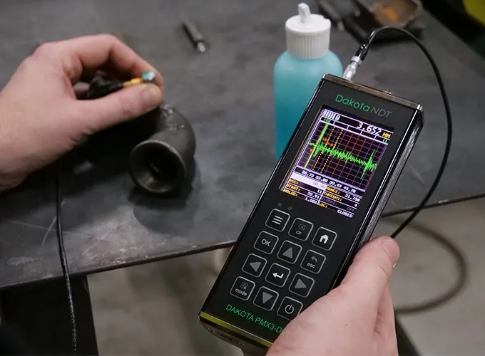
- Dakota FX70-DL — portable flaw detector with extended battery life and a display that remains highly visible even in direct sunlight. It is the typical choice for inspections on site, on ships, on outdoor structures and on in-service pipework.
- Dakota FX81-DL — benchtop version with a larger display, ideal for quality control laboratories and fixed production acceptance stations.
To help you choose between portable and benchtop, we have published a dedicated technical comparison: Dakota FX70-DL vs FX81-DL: portable or benchtop flaw detector?. A practical step-by-step guide to using the FX70-DL for AWS D1.1 inspections is available in Ultrasonic weld inspection to AWS D1.1 with the Dakota FX70-DL.
Dedicated angle probes and accessories

For UT weld inspection, a set of dedicated probes is essential. The Dakota range of transducers for flaw detectors includes:
- Angle probes for transverse waves (shear waves) with fixed angles of 45°, 60° and 70° — full coverage of the weld bead using the skip method.
- Straight-beam probes (0°) for preliminary checking of the base material and reference thickness measurement before inspection.
- Dual-element probes for near-surface inspections and on geometries with low remaining thickness.
- Shielded cables in Lemo, BNC and Microdot configurations, and calibration blocks such as IIW V1, V2 and step blocks for daily instrument calibration.
Certified calibration blocks and couplants for standard and high-temperature applications and for vertical or overhead surfaces are also available from stock.
Typical industrial applications
- Structural steelwork — inspection of welds on bridges, steel buildings, industrial sheds and offshore structures to AWS D1.1 / EN 1090.
- Pressure vessels — pre-commissioning and periodic inspections to ASME Section VIII and PED 2014/68/EU.
- Process piping — girth weld inspection on pipelines, refineries and chemical plants to ASME B31.3 and API 1104.
- Railway industry — inspection of axles, wheels and rolling stock frames.
- Shipbuilding — hull welds and critical structures in accordance with RINA, Lloyd’s and DNV rules.
- Heavy boilermaking — welds on shells, heads and casings for steam generators and heat exchangers.
Difference between a flaw detector and a corrosion gauge
A distinction that often arises when selecting instruments: the UT flaw detector identifies and sizes internal discontinuities in the volume of the material (cracks, inclusions, lack of fusion), whereas the corrosion gauge quantifies the remaining thickness of a wall subject to corrosion. The two techniques use the same ultrasonic physics but serve different purposes, and in many industrial applications it is advisable to have both instruments.
For an in-depth technical analysis: Corrosion gauge vs flaw detector: when you need both.
Distribution, support and operator training
RODER SRL supplies Dakota NDT instruments with Italian stock, NIST-traceable factory calibration and technical support in Italian. On-site operational training sessions are also available to prepare Level 1 and Level 2 UT operators for the specific use of Dakota flaw detectors in welding applications.
For full technical documentation, product data sheets, real applications and case studies: www.ultrasuonindt.it.
Related reading:
- On roder.it: Ultrasonic weld analysis (analysis of the plastic welding process with slow-motion cameras)
- On roder.it: Ultrasonic thickness gauges
- On ultrasuonindt.it: AWS D1.1 — UT requirements and instrumentation
- On ultrasuonindt.it: Practical guide to AWS D1.1 inspection with the Dakota FX70-DL


You must be logged in to post a comment.