





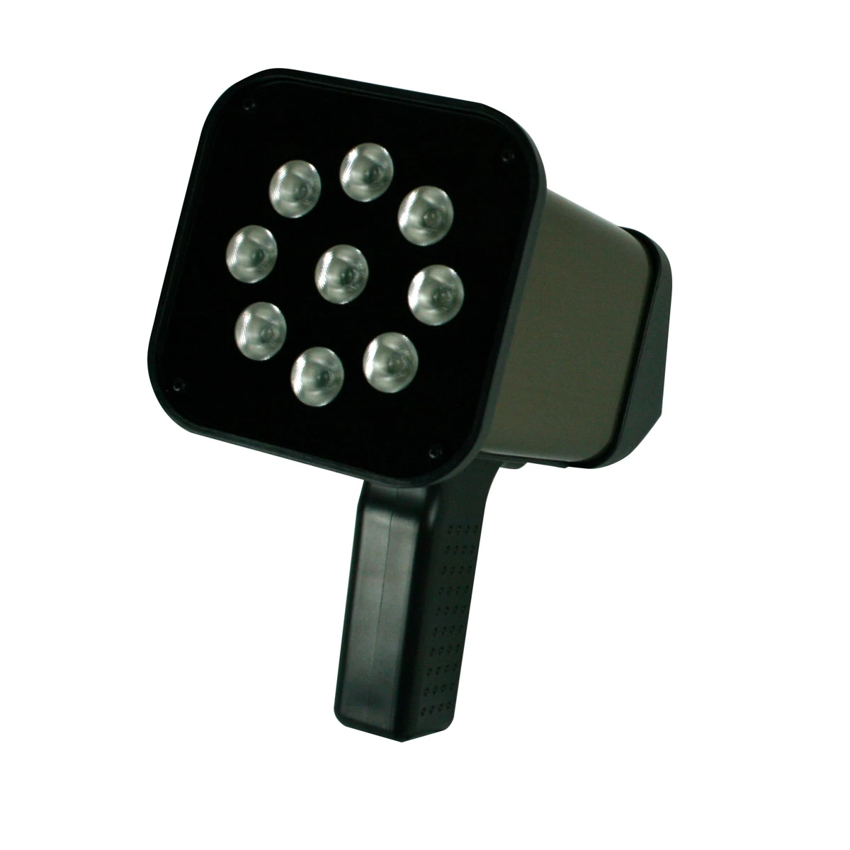
Optical stroboscopy is a non-contact measurement and inspection technique: by illuminating a moving object with flashes of light at an adjustable frequency, it is made to appear stationary or slowed down, so that its rotational speed can be measured and its details inspected.
- Stroboscopic effect: a moving object that appears stationary
- Non-contact RPM measurement: no wear or marks
- Adjustable frequency: FPM and Hz, wide range
- LED or xenon lamp: long life or intense flash
- Phase delay: analysis at any point of the cycle
- Flash duration: sharper images
- Synchronisation: external sensor input
Stroboscopy exploits persistence of vision: when a rotating or reciprocating part is illuminated by very short, repeated flashes of light, the eye perceives a sequence of “frozen” images. If the flash frequency coincides with the rotation frequency of the object (or with a submultiple of it), each flash illuminates the object in the same position every time and it appears stationary. By finely adjusting the frequency, the motion can be made to appear slowed down, forwards or backwards.
Because the measurement is purely optical and non-contact, it introduces no friction or wear, leaves no marks on the surface and does not require the machine to be stopped, making it ideal for process control and predictive maintenance. RODER offers the technology with the range of LED and xenon Shimpo stroboscopes.

Would you like help choosing the right product ?
What the stroboscopic effect is
The stroboscopic effect is based on the relationship between the flash frequency and the frequency of the motion. When the two frequencies are equal, the object is always illuminated at the same phase of its cycle and appears motionless. If the flash frequency is an exact multiple or submultiple of the rotation frequency, several equally spaced images or a single stationary image are seen. The frequency is expressed in flashes per minute (FPM) or in hertz (Hz); Shimpo stroboscopes cover very wide ranges, from 30–60 up to 120,000 FPM in the LED models.
How rotational speed (RPM) is measured
To measure the speed of a rotating part, the flash frequency is gradually increased until a single stationary image is obtained. It is important to check that you are not on a submultiple: at half the frequency, for example, the image may appear stationary depending on the symmetry of the object. Once the frequency corresponding to the first unambiguous stationary image has been found, the reading in FPM is equal to the speed in revolutions per minute. The ×2 / ÷2 functions and the +/− fine tuning of the Shimpo models speed up this search.
LED lamp and xenon lamp
The light source determines performance and field of use. LED technology (used by the ST-4000, ST-5000/ST-5100, DT-366, DT-326 and ST-320BL) offers a very long life with no bulb replacement and very wide frequency ranges (up to 120,000 FPM). The xenon lamp (models DT-735 and DT-311D) produces an extremely short (10–30 µs) and intense flash, very effective for detail, with a typical range of up to 12,000 FPM.
Phase delay and flash duration
Two advanced adjustments extend the analysis. The phase delay (in degrees, up to 0–359° on advanced models) makes it possible to “freeze” the object at any point of its cycle, in order to observe all its phases progressively. The adjustable flash duration reduces motion blur and produces sharper images for detailed inspection. With the external sensor input, the flash frequency can also be synchronised automatically with the speed of the process.
Applications of optical stroboscopy
- Predictive maintenance of motors, shafts, fans and impellers
- Inspection of moving gears, cams, belts and pulleys
- Quality control in printing, packaging and textiles
- Vibration analysis and balancing checks
- Non-contact RPM checks on production lines
For practical use in process control, see the in-depth article Monitoring RPM and rotational speed of machines.
RODER products for optical stroboscopy
RODER distributes the complete range of Shimpo stroboscopes, LED and xenon, portable battery-powered or mains-powered, with a UV light version for UV ink printing: ST-4000, ST-5000/ST-5100, DT-735, DT-311D, DT-366, DT-326 and ST-320BL.
Stroboscopy and vibration analysis
As well as measuring RPM, stroboscopy is an effective tool for vibration analysis. By adjusting the flash frequency close to the rotation frequency, components that vibrate or have play appear to move slowly, making visible resonances, loosening, misalignments and imbalances that are difficult to observe with the naked eye. This visual analysis, carried out while the machine is running, helps to diagnose the cause of abnormal noise and vibration and to verify the outcome of balancing or tightening work.
Safety and sectors of use
Shimpo stroboscopes use LED or xenon lamps, with no harmful laser light: this simplifies in-line use and reduces optical safety requirements. The technology is used across the printing, packaging, textile, automotive, cable, paper, steel, chemical and medical sectors, wherever it is necessary to check speed or inspect fast-moving parts without stopping production. The combination of measurement and inspection in a single portable instrument makes it a valuable aid for maintenance and quality control departments.
Frequently asked questions
It is a non-contact measurement and inspection technique that illuminates a moving object with flashes of light at an adjustable frequency: when the flash frequency coincides with that of the motion, the object appears stationary, allowing its rotational speed to be measured and its details to be inspected.
The flash frequency is adjusted until the rotating part appears as a single, unambiguous stationary image: the frequency in FPM is equal to the speed in revolutions per minute, checking that you are not on a submultiple.
LED models offer long life and very wide ranges (up to 120,000 FPM); xenon models produce a very short, intense flash (10–30 µs) ideal for detail, up to 12,000 FPM.
No: Shimpo stroboscopes use LED or xenon lamps, with no harmful laser light.
It makes it possible to “freeze” the object at any point of the cycle (0–359°) in order to analyse all the phases of the motion progressively.
Related products
The RODER instruments for this application. Go to the relevant catalogue pages for models, technical data and documentation.

Contacts & Information
Contact for general information : info@roder.it
Machine Vision Division of RODER : www.rodervision.com
RODER Instruments Division : www.innovacheck.com
More about RODER : about us
The information contained in this website is provided for information purposes only. Although it has been prepared with the greatest care, it does not constitute a contractual offer or a binding commitment to supply. It may contain transcription, translation or typographical errors. For precise and up-to-date information, please contact our company directly.
Note: Some images on this website have been intentionally generated using artificial intelligence (AI). This is because, for many applications and projects, photographs of the actual installation or system cannot be disclosed owing to confidentiality agreements, contractual clauses and non-disclosure agreements (NDAs).
You must be logged in to post a comment.